
For this project, I wanted to make a compact portable plotter using 2 motors from CD/DVD Drives.
I wanted to give it some memory where it can store some plots, and have a menu system to set some basic settings and be able to chose plots stored in memory.


I use
FreeCAD 0.18 to
design my 3D Prints, and
KiCad 5.0.2 to design
my PCB.
Both these programs can integrate with each other. They are open source and I recommend them.
Both these programs can integrate with each other. They are open source and I recommend them.
My previous Mini Plotter Ver. 1 looked like this:
Version 1
version 1.3
For a list of the purchased modules for this project look here: Module List
For a list of 3D Printed Parts (PLA) look here: Printed Parts.
Motor Shield Modification:

The motor shields are a breakout boards for the L293D (dual Half-bridge driver) with a 78M05. (5 volt regulator)
I don't want to use them as they are, I'm going to modify them. (it was cheaper this way than making my own)
Here is a sketch showing them in place. (they end up under the board I will make):

The main modification to the shields, is the removal of the 5 volt regulator,
care needs to be taken when removing these as they will be used later.
The reason for removing them is: I want to wire them in a different
configuration.
I will be using them to control the amperage as well as the voltage.
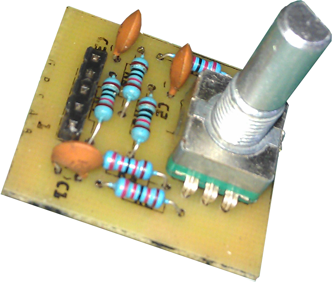
Here is a photo of one I have modified, I have highlighted areas I have changed:

If you are not making it to fit my printed plotter then as I say earlier, only the voltage regulator needs to be removed. I have modified other parts to make it fit easier.
Depending on how the motherboard is made, the row of 8 pins could be a row of sockets.
Which ever, when the motherboard is fitted over these drivers, there is matching pins or socket that connect together.
Also the motherboard covers one of the drivers completely, so on one of the driver boards, the row of 4 pins to the stepper motor needs to be a horizontal set. (see sketch showing them fitted above)
I will be making a motherboard to fit over the top of these and hold the Arduino NANO that will be controlling them. (I will also add other things for future)
The original Driver Shield was wired up like this:

You can see that the L7805 is wired to just regulate the voltage.
After the modification it will be something like this:
The stepper motors I am using for this project are motors I repurposed from
some CD/DVD drives.
The only data I could find for these type of motors was from a data sheet for a
PL15S-020. (I will assume other makes are similar)
If we do a little maths: V=ri, 5 volt divided by 10 ohms = 0.5 Amps
As I could check the resistance of my motors and found them to have 12 ohm
resistance.
I will work on the assumption mine require 0.4A. (5/12=0.42A)
They probably are designed to take 0.5A, but: they are normally mounted to a large metal frame that acts like a massive heat sink.
My steppers are going to be mounted to plastic. (PLA)
They probably are designed to take 0.5A, but: they are normally mounted to a large metal frame that acts like a massive heat sink.
My steppers are going to be mounted to plastic. (PLA)
(see 78M05's in circuit below)
The resistors used will need to be 12.5 ohm 2 Watt.
(load = regulator voltage / resistor) R=5/0.4=12.5, (W=Vi) 5x0.4=2
I found some 12 ohm. Search eBay: 2W Metal Film Resistor.
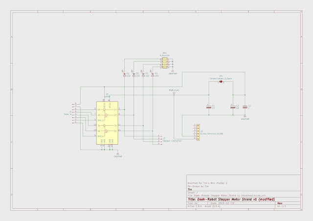
This is the circuit of the Motherboard I will be making:

I have added the L7805 to power the servo or a laser I hope to add at a later date.
The L7805 is a little under powered for the servo, one day I want to come up with a better way of controlling the pen.
A Rendered 3D sketch (this sketch may change as I find better configurations):

You can see from the sketch above I use the two voltage regulators taken from the driver boards.
These will get hot, I haven't fitted heatsinks. The board I designed here is double sided and has copper fill on the underside to help dissipate the heat, a heat sink could be fitted under, but it is not required.

The Voltage Regulators removed from the Driver Boards are 78M05 which are 500mA devices, with max. operating temperature 125 deg. C. As we are setting them at 400mA (close to max.) I do not recommend touching them when in use.
But wiring the power to the stepper motors in this way means that the regulator gets hot (which they are designed to do) and the stepper motors don't.
A Rotary Encoder bought of the web could be used as is, but this project uses all the memory on the Arduino NANO due to the menu. (menus use a lot of text )
The modules on the web vary slightly, (made as cheep as possible) some don't have pullup resistors on all the switch pins. They defiantly don't have any de-bounce circuitry.
Code can be used for the de-bounce and internal pull up resistors could be set, but as I say, memory is a premium on this project.
So I make my own board with pullup resistors on all switch pins and because I have put interrupts on all three, all have a resistor/capacitor de-bounce.


I have made a single board to house the three AT24C256 memory IC's.
I haven't made it with jumpers for the addresses of each IC, I set the addresses in the PCB Circuit. (50, 51 and 52)


I used a stackable header socket so that it fits between the motherboard and the OLED Screen.
I only have 2 memory IC's at the moment, but on these two have managed to fit 18 plots on them.
I can now plot the following without it plugged into my computer.
All I need is to add power from my little power pack I made.

Recommend 9v. (lowest it will run at is 7.5v)
At standstill draws 90mA.
Drawing draws 650mA.
Servo movement peaks at 800mA.
With 12v. (Max, don't recommend going higher)
At standstill draws 100mA.
Drawing draws 900mA.
Servo movement peaks over 1A. (If the plot has a lot of servo movement, the L7805 will get hot)
I have ordered some more memory IC's, when I get them I am going to write some code to make the plot files smaller, to enable more to be saved to the memory.
Also I want to add the alphabet.
Also thinking of making a laser attachment, that's why I put a MOSFET in the circuit.
A closeup of the boards fitted:

Added some ASCII Characters to the memory.

I also designed it to take a laser.
I am still doing my blog on my main XY Plotter atm, so I will post details
when I get time or if some one takes interest in it.
(if anyone wants to make it and would like the stl files, just ask)
I have a web site as well:
Tim's Place
I am making a new version: https://www.youtube.com/watch?v=YSE00Mr2BqY&t=1783s
ReplyDelete