
This is how I added more memory to my Arduino NANO that I am using to control my Mini Plotter 2 and compress G-Code so that I was able to save more plots on the memory.
I am going to assume you know how to program an Arduino, also you have done many of the examples on the Arduino web site: Arduino Standard Libraries.
The memory I am going to use is: ATMEL 24C256 it is a EEPROM (Electrically Erasable Programmable Read-Only Memory )
Data about it can be found here: Data
The important things to know about it is:
32K x 8 (256 Kbit)
2-Wire Serial Interface, I2C Compatible
400 kHz and 1 MHz clock compatibility
Self-Timed Erase and Write Cycles (5 ms max.)
Page Size (bytes) 64
Op. Volt Range (V) 1.7 to 5.5
This means:
The memory is divided up into 8 bit chunks (1 byte), so we can store 32K bytes of information, one byte at each address ( 0 to 31999).
We can connect it to our Arduino NANO using the I2C bus.
We have a choice of communicating with it at 400kHz or 1MHz. (on the Arduino Nano I will communicate at 400kHz).
The Write Cycles may take 5ms to write the data to an Address, this has to be accounted for when sending data (when writing the code, delays need to be added).
A Page Size of 64 bytes, means in certain cases 64 bytes of data can be sent at one time (more about this in data sheet).
Voltage Range 1.7 to 5.5. this is ok with the Arduino Nano (Nano data is at 5 volt).
Connection:

Vcc and GND are power and ground respectively.
A0, A1 and A2 are the address pins, setting these either HIGH (connect to power) or LOW (connect to Ground) changes the address of the device enabling up to 8 of these devices to be placed on one I2C Line.
WP when connected HIGH (connected to power) will Write Protect the data on the device. This should be connected LOW (connected to ground) so that data can be written.
SCL and SDA are the Clock and Data lines of the I2C bus. (all SCL connect to each other, all SDA connect to each other)
SCL and SDA are the Clock and Data lines of the I2C bus. (all SCL connect to each other, all SDA connect to each other)
A Note about I2C Lines:
Both lines should be pulled HIGH with a resistor to each.
Only one resistor on each, even if there are many devices on the I2C bus.
As rule, If I am making a motherboard for the master device, I will put the resistors on that.
Some times if I am making a project that is modular I will use a bus-board similar to this:


I have a box full of 10k ohm resistors so I use two of them.
However there are formula for calculating the maximum and minimum value to use, check this: specification, section 7.
Connecting to the Arduino Nano:
I made my self a special pin sheet to help me remember the special pins when I start a project, so I know what's needed when I am going to use certain devices.

Code:
The code needed to communicate via the I2C pins to other I2C devices can be added to your code by adding the Arduino wire library. (other examples of using I2C can be found here)
So using the Arduino wire library we can write code to Read and Write Data to the EEPROM.
After writing our code enabling the Arduino Nano to communicate with the EEPROM, we need to communicate with the Arduino Nano to tell it what to Read/Write to/from the EEPROM.
We do this from our PC via the USB.
We could do this using the Arduino IDE Serial Monitor, but typing every thing is tedious, I would rather send a file.
So we need a program that runs on our computer that can communicate with the Arduino.
Lets have a picture of what we need:

I assume you can write your own programs so I will only be highlighting things I think are critical.
The program I wrote for the Arduino Nano can be downloaded Here: Tims_Arduino_Memory_Writer_Firm.ino The program is well commented as it contain all my workings, to work out how to do it.
A Note about the IDE I use and the screen shots of my code.
I use MS Visual Studio Community Edition with an Extension for Arduino.
If you use VS, I do recommend Visual Micro.
Lets start with Arduino Nano to the EEPROM ATMEL 24C256 .
As mentioned you need to #include <Wire.h>
You need to know the address of the EEPROM (This is the address of the device on the I2C bus).
I usually #define EEPROM_ADD 0x50
In the void setup(){…….}:
You need to start I2C communication with: Wire.begin();
Set the communication speed with: Wire.setClock(400000);
Communicating:
Communicating like any other language has to follow certain rules, I will talk about rules later.
To talk to the EEPROM we need to get its attention, let it know, it, is the device we want to talk to.
To do this we send the command Wire.beginTransmission(EEPROM_ADD);
Basically what this is saying: I want to communicate with the device at the address of 80 (0x50).
Now that we have the attention of the device (EEPROM) we can send information to it, because it knows any information sent along the I2C bus, is for it.
Also it knows that the next bytes sent should be the address where the data is to be read or written. (this is one of the rules)
So the next thing to do is send the address of the byte where we want to start reading or writing data.
I need to explain something about the address of the data, it could be 31999. (it has 32k byte of memory)
So the data address is a 16 bit value, two bytes, and we can only send one byte at a time.
That means we have to send the data address in two halves.
Also I want to mention the Self-Timed Erase and Write Cycles (5 ms max.) again.
If we send a command to Write, we need to wait for it to do it.
So after sending Wire.beginTransmission(EEPROM_ADD);
I wait a millisecond.
Then send the first half of the address.
As this is a write command I wait 6ms
Then send the second half of the address and wait 6ms.
So the code so far looks like:
Wire.beginTransmission(EEPROM_ADD);
delay(1);
Wire.write((int)(dataAddress >> 8));
delay(6);
Wire.write((int)(dataAddress & 0xFF));
delay(6);
Now we can either Read or Write a byte at this address.
I need to explain something about Page Write, it is possible to Write more than one byte at a time.
It would require a little more code (not much) and make writing quicker, but as this is all about saving space in the Nano's memory, and the extra time is not an issue, I will be Writing data one byte at a time. Also the majority of the data (G-Code commands) that I will be saving, will only be three bytes long.
If I am Writing Data the above will be put in a "for loop" something like this: for (byte i = 0; i < 3; i++) {……………} and the command would be Wire.write(byte(buffer[i])); and because I am Writing, I add a delay of 6ms.
After Writing the data we send the command: Wire.endTransmission(); and wait 1ms.
This lets the device know we are done and frees up the I2C bus to any other device that may be connected. (my Mini Plotter Project has two more EEPROM's and an OLED screen on the I2C bus)
If I am Reading Data I would end transmission at this point, by sending the command: Wire.endTransmission(); and wait 1ms, because to Read data from a device, we can send a request using the devices address.
The Wire Library has a command to request a specific device for a specified amount of data.
All we had to do was set the address location first.
All we do now is tell which device we want to give us the data and how much to give us.
We send : Wire.requestFrom(EEPROM_ADD, dataLength); and wait 1ms, then add a while (Wire.available()) {………..} and collect the data sent.
To collect the data sent, we use the command Wire.read(); to populate a byte array.
So the two functions (simplified) would look like:
//WRITE DATA
void writeData(unsigned int dataAddress, unsigned int dataLenth) {
for (byte i = 0; i < dataLength; i++) {
Wire.beginTransmission(EEPROM_ADD);
delay(1);
Wire.write((int)(dataAddress >> 8));
delay(6);
Wire.write((int)(dataAddress & 0xFF));
delay(6);
Wire.write(byte(data[i]));
delay(6);
Wire.endTransmission();
delay(1);
plotFileAddress++;
}
}
//READ DATA
void ReadData(unsigned int dataAddress, unsigned int dataLenth) {
Wire.beginTransmission(EEPROM_ADD);
delay(1);
Wire.write((int)(dataAddress >> 8));
delay(6);
Wire.write((int)(dataAddress & 0xFF));
delay(6);
Wire.endTransmission();
delay(1);
Wire.requestFrom(EEPROM_ADD, dataLength);
delay(1);
byte byteCount = 0;
while (Wire.available()) {
byte c = Wire.read();
delay(1);
data[byteCount] = char(c);
byteCount++;
}
}
Before anyone mentions it - I know when Writing, I should only have to set the address of the first byte, and put only the Write command in the loop, (similar to read) but it didn't work for some reason. (the EEPROM should automatically set it's self to the next address when reading and writing)
So that's the basics for getting the Arduino Nano to Read and Write to the EEPROM, look at the code to see more.
In my code there are more functions than are needed, the one I finaly used for writing to the EEPROM is: void writeCommand() {…...}
The one I use to read is: char readWord(int dataAddress, int dataLength){…….}
Using the readWord will pint characters to the Serial Monitor.
Before reading what's on the EEPROM we need to write something to it.
So lets look at communication between the Arduino and the PC.
So that the Arduino knows what to write to the EEPROM.
If you have looked at my code (Tims_Arduino_Memory_Writer_Firm.ino ) then you will find a function (void ReadSerial() {...}) this deals with communication via the USB.
This function looks like many found on the web on other projects, but I just want to mention some important parts of it.
Lets look at it:

It has an "if else" this just separates thing between:
"There is data to be read" and "There is no data to be read".
When there is data available, there is the: if (!(c == '\r' && p == '\n')) {...}
Notice I have the && (and) not the || (or) in this statement, also it is checking the variable p for '\n'.
I mentioned I was going to talk about rules, so at this point I need to talk about one of the rules in G-Code script.
A simple bit of G-Code to draw a box would look like this:
G00 X100.0 Y100.0
G01 X200.0 Y100.0
G01 X200.0 Y200.0
G01 X100.0 Y200.0
G01 X100.0 Y100.0
G00 X0.0 Y0.0
The rule I want to mention here, is: Each command is separated buy a "Carriage Return" (\'r') and a "New Line" ('\n').
Notice I say AND, not OR.
A lot of people get a bit lazy here and just read one character at a time and check if that character is either a "Carriage Return" or a "New Line" using a statement like: if (!(c == '\r' || c == '\n')) {…}
This is quite OK, it's not a problem when reading G-Code script.
BUT, as the title says, this is also about compacting a command like the ones shown above (15 characters) to just three characters.
When compacting the G-Code I will be using the full 256 extended character table, one of the three characters may involve using the character for "Carriage Return" or the character for "New Line".
The chances the compression will create a string with '\r' followed by '\n' are extremely high. (so I think I am fairly safe)
When the compressed command is sent to the Arduino to be saved on the EEPROM it is followed by a "Carriage Return" and a "New Line" ("\r\n").
So that why I need to PEEK a character ahead to check and see if a "Carriage Return" is followed by a "New Line", if it is, I know it's the end of the message, if it is not, then I know it is to be saved.
I think it is best to do the next bit in order. That is:
Set some rules part 1. (to free some space on the Arduino Nano)
Save data.
Use the rules part 1 to let the Arduino use the data stored.
Set some rules part 2. (how am I going get G-Code to just 3 bytes)
Apply Rules to G-Code.
Compress and save G-Code.
Set some rules part 3. (need to let the menu system on the Arduino know where to find the plot files)
Save Name and Location of Plots.
Follow rules on the Arduino to find and plot, "Plot Files".
So our first rule part 1. (to free some space on the Arduino Nano)
Anyone who has ever made a menu system on there project using an Arduino Nano, will know that memory soon disappears when using strings.
As the fixed strings use in a menu system don't change, one place to put these is in the programs memory, (simply put, the part memory that dose not change) using the "F" function. e.g. display.print(F("Hello"));
But some times this part of the memory get used up as well, so we need some where else to put the strings.
For example:
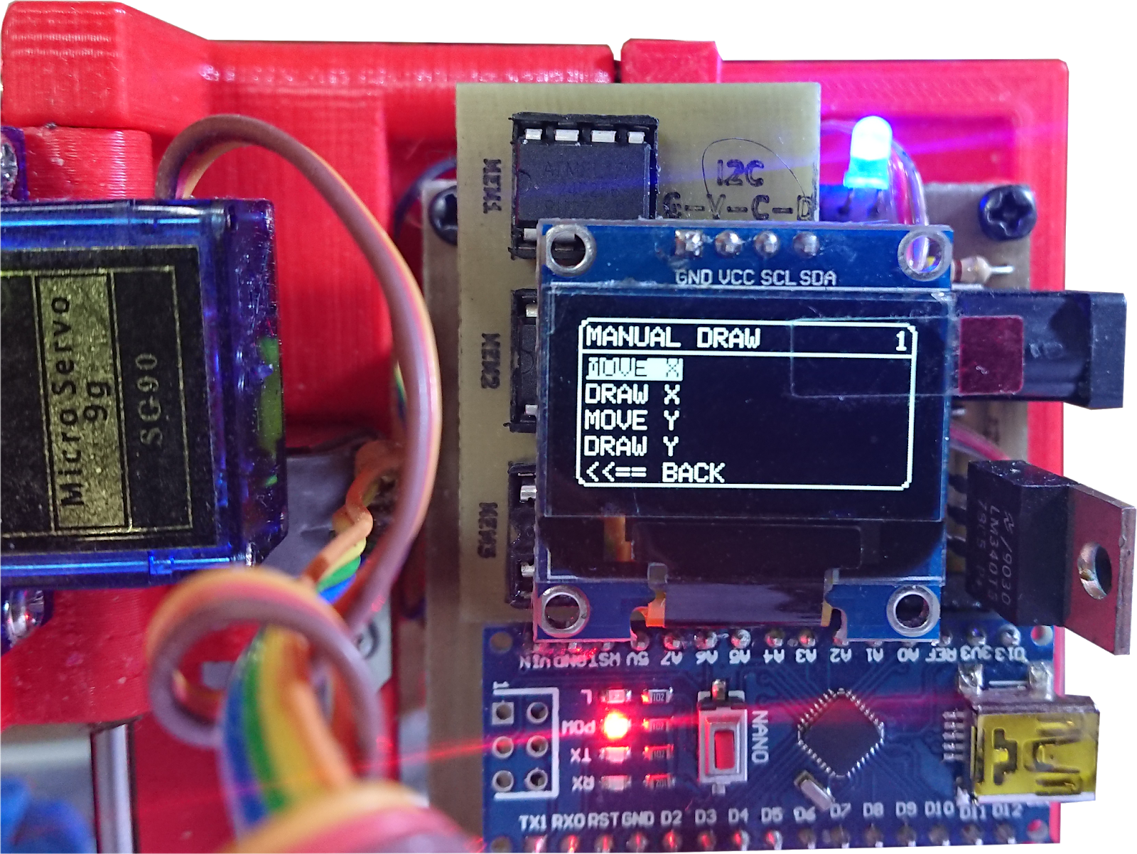
My Mini Plotter Project has a menu system that needs to show quite a lot of text.


Each character uses 1 byte of memory, if we look at the above menu's I have shown, it adds up to about 150 bytes. This might not sound a lot, but if we now move down to the Choose Plot Menu.
 The Plot Menu needs to scroll though all the plot names saved on the EEPROM.
As I have allocated room for 166 plot names, each 10 characters long, this adds up to another 1660 bytes of text.
Also the menu system I have come up with, is based on the hexadecimal (base 16) numbering system, my menu systems page numbers are numbered by a 32 bit hexadecimal number, meaning from the main menu I can have a page with up to 16 choices, each of those choices can have 16 choices, each of those choices can have 16 choices, each of those choices can have 16 choices, and so on up to 8 times.
As we can't compress characters they are just saved as they are. A "byte" and a "char" when saved to the EEPROM are the same thing, it's only when you print them that the Arduino shows them as a character or a number.
In my code there are more functions than are needed, the one I finaly used for writing to the EEPROM is: void writeCommand() {…...}
The one I use to read is: char readWord(int dataAddress, int dataLength){…….}
Using the readWord will pint characters to the Serial Monitor.
Before reading what's on the EEPROM we need to write something to it.
So lets look at communication between the Arduino and the PC.
So that the Arduino knows what to write to the EEPROM.
If you have looked at my code (Tims_Arduino_Memory_Writer_Firm.ino ) then you will find a function (void ReadSerial() {...}) this deals with communication via the USB.
This function looks like many found on the web on other projects, but I just want to mention some important parts of it.
Lets look at it:

It has an "if else" this just separates thing between:
"There is data to be read" and "There is no data to be read".
When there is data available, there is the: if (!(c == '\r' && p == '\n')) {...}
Notice I have the && (and) not the || (or) in this statement, also it is checking the variable p for '\n'.
I mentioned I was going to talk about rules, so at this point I need to talk about one of the rules in G-Code script.
A simple bit of G-Code to draw a box would look like this:
G00 X100.0 Y100.0
G01 X200.0 Y100.0
G01 X200.0 Y200.0
G01 X100.0 Y200.0
G01 X100.0 Y100.0
G00 X0.0 Y0.0
The rule I want to mention here, is: Each command is separated buy a "Carriage Return" (\'r') and a "New Line" ('\n').
Notice I say AND, not OR.
A lot of people get a bit lazy here and just read one character at a time and check if that character is either a "Carriage Return" or a "New Line" using a statement like: if (!(c == '\r' || c == '\n')) {…}
This is quite OK, it's not a problem when reading G-Code script.
BUT, as the title says, this is also about compacting a command like the ones shown above (15 characters) to just three characters.
When compacting the G-Code I will be using the full 256 extended character table, one of the three characters may involve using the character for "Carriage Return" or the character for "New Line".
The chances the compression will create a string with '\r' followed by '\n' are extremely high. (so I think I am fairly safe)
When the compressed command is sent to the Arduino to be saved on the EEPROM it is followed by a "Carriage Return" and a "New Line" ("\r\n").
So that why I need to PEEK a character ahead to check and see if a "Carriage Return" is followed by a "New Line", if it is, I know it's the end of the message, if it is not, then I know it is to be saved.
I think it is best to do the next bit in order. That is:
Set some rules part 1. (to free some space on the Arduino Nano)
Save data.
Use the rules part 1 to let the Arduino use the data stored.
Set some rules part 2. (how am I going get G-Code to just 3 bytes)
Apply Rules to G-Code.
Compress and save G-Code.
Set some rules part 3. (need to let the menu system on the Arduino know where to find the plot files)
Save Name and Location of Plots.
Follow rules on the Arduino to find and plot, "Plot Files".
So our first rule part 1. (to free some space on the Arduino Nano)
Anyone who has ever made a menu system on there project using an Arduino Nano, will know that memory soon disappears when using strings.
As the fixed strings use in a menu system don't change, one place to put these is in the programs memory, (simply put, the part memory that dose not change) using the "F" function. e.g. display.print(F("Hello"));
But some times this part of the memory get used up as well, so we need some where else to put the strings.
For example:
My Mini Plotter Project has a menu system that needs to show quite a lot of text.


Each character uses 1 byte of memory, if we look at the above menu's I have shown, it adds up to about 150 bytes. This might not sound a lot, but if we now move down to the Choose Plot Menu.

As I have allocated room for 166 plot names, each 10 characters long, this adds up to another 1660 bytes of text.
Also the menu system I have come up with, is based on the hexadecimal (base 16) numbering system, my menu systems page numbers are numbered by a 32 bit hexadecimal number, meaning from the main menu I can have a page with up to 16 choices, each of those choices can have 16 choices, each of those choices can have 16 choices, each of those choices can have 16 choices, and so on up to 8 times.
As we can't compress characters they are just saved as they are. A "byte" and a "char" when saved to the EEPROM are the same thing, it's only when you print them that the Arduino shows them as a character or a number.
First find all the "Text" Strings in our program that do not change value.
Next make a text file and add all the words and phrases end to end as one big string, with the exception of the plot names, (I am going to save the plot names differently) and make a note of where in the string each word or phrase starts in the string, and how long the word or phrase is.
Include any spaces in a phrase.
We know that the serial buffer for the Arduino Nano is 64 bytes, so we don't want to send a string longer than that.
As mention already the program I have made to send data to the Arduino Nano, sends a "carriage return" and a "new line" at the end of a transmission.
As I don't like to use the Arduino Nano to its limits, I am only going to send 32 bytes at a time.
So the simplest way to add a "carriage return" and "new line" at the end of every 32 characters, is, do it in the text document.
So to recap, our first rules:
Find all text in our program, and add the text, to a text file, end to end (include spaces in phrases).
Make a note of where each word or phrase starts, and how long each word or phrase is.
In the text document press return on the keyboard every 32 characters.
Only three rules, but they are important and must be followed.
So I end up with a text document that contains this:
MAINMANUAL DRAWCHOOSE PLOTSETTIN
GSINFORESETMOVE XDRAW XMOVE YDRA
W Y<<== BACKSPEEDTOOL--Tim's Min
i Plotterok=== Motors Off ===Ver
sion: Basic Gcode CommandsM03 -
Tool On/DownM05 - Tool Off/UpM18
- Motors OffSystem ResetM100 -
this Info messageR01 - Reset Plo
tterBy Tim Jackson.1960=========
======= test A
I have called it: Memory_Words.txt the text file is 329 bytes. (I am going to free up this memory space in my program)
My notes when doing this is as follows:
(0, 4); // MAIN
(4, 11); // MANUAL DRAW
(15, 11); // CHOOSE PLOT
(26, 8); // SETTINGS
(34, 4); // INFO
(38, 5); // RESET
(43, 6); // MOVE X
(49, 6); // DRAW X
(55, 6); // MOVE Y
(61, 6); // DRAW Y
(67, 9); // <<= = BACK
(76, 5); // SPEED
(81, 4); // TOOL
(85, 2); // --
(87, 18); // Tim's Mini Plotter
(105, 2); // ok
(107, 18); // == = Motors Off == =
(125, 9); // Version:
(134, 20); // Basic Gcode Commands
(154, 18); // M03 - Tool On/Down
(172, 17); // M05 - Tool Off/Up
(189, 16); // M18 - Motors Off
(205, 12); // System Reset
(217, 24); // M100 - this Info message
(241, 19); // R01 - Reset Plotter
(260, 19); // By Tim Jackson.1960
(279, 16); // ================
(295, 10); // (10 spaces)
(305, 6); // test A
Saving the data:
I have written a program to send all the words and phrases to the EEPROM.
I forgot to mention some rules.
To write this program I need to know where I want to save the data on the EEPROM.
I decided:
Words and Phrases will be saved in the first 500 bytes (0 to 499) of the EEPROM.
Plot Names and information on where the Plot data is stored, will be in the next 2500 bytes (500 to 2999) of the EEPROM.
Plot data will be saved in the rest of the EEPROM (3000 to 31999).
Plot data will be saved in the rest of the EEPROM (3000 to 31999).
I have not made the program idiot proof, that is, do the wrong things and it may crash. (after all it was originally just for me)
Also window may give warnings when you install it. (I used Microsoft Visual Studio Community Edition to write it and I haven't signed it)

I have made it a bit flexible, but have added some pre-sets. Tim's EEPROM_Writer.zip
To use this:
You need an Arduino (any type) plugged into you computer via a USB.
The Arduino must have Tims_Arduino_Memory_Writer_Firm.ino Installed.
The EEPROM needs to be connected to the Arduino.

 First we need to connect to the Arduino.
In the Coms section, choose the correct COM Port the Arduino is connected to.
Set the communication speed to 115200.
Click the connect button. (if it connects, the status will be written green)
Note! Only 1 device can be connected to a COM Port at a time, make sure your Arduino IDE Serial Monitor is not connected.
Once connected, "Browse" for the file: Memory_Words.txt (obviously after you have downloaded it)
To send this file, the checkbox "Send Words" must be ticked.
This is a pre-set, you will notice that the settings for "Start Address" and "Page Length" Have been set, and cannot be changed.
This is so things happen according to the rules we have talked about.
Now click "Send Settings" button. when the settings on the Arduino have been set, a conformation should be shown in the "Feed Back" window.
After conformation, click the "Send" button.
Where it currently shows "Done" on the screenshot, data being sent should appear.
When all is done, "Done" should be displayed again.
Next part. Use the rules part 1 to let the Arduino use the data stored.
OK, there is a copy of all the "text" used in our program on the EEPROM.
We now need to tell our Arduino how to use it.
Also window may give warnings when you install it. (I used Microsoft Visual Studio Community Edition to write it and I haven't signed it)

I have made it a bit flexible, but have added some pre-sets. Tim's EEPROM_Writer.zip
To use this:
You need an Arduino (any type) plugged into you computer via a USB.
The Arduino must have Tims_Arduino_Memory_Writer_Firm.ino Installed.
The EEPROM needs to be connected to the Arduino.


In the Coms section, choose the correct COM Port the Arduino is connected to.
Set the communication speed to 115200.
Click the connect button. (if it connects, the status will be written green)
Note! Only 1 device can be connected to a COM Port at a time, make sure your Arduino IDE Serial Monitor is not connected.
Once connected, "Browse" for the file: Memory_Words.txt (obviously after you have downloaded it)
To send this file, the checkbox "Send Words" must be ticked.
This is a pre-set, you will notice that the settings for "Start Address" and "Page Length" Have been set, and cannot be changed.
This is so things happen according to the rules we have talked about.
Now click "Send Settings" button. when the settings on the Arduino have been set, a conformation should be shown in the "Feed Back" window.
After conformation, click the "Send" button.
Where it currently shows "Done" on the screenshot, data being sent should appear.
When all is done, "Done" should be displayed again.
Next part. Use the rules part 1 to let the Arduino use the data stored.
OK, there is a copy of all the "text" used in our program on the EEPROM.
We now need to tell our Arduino how to use it.
I have already spoke about the function to read data from an EEPROM, but now its time to make a function to use.
Lets start with what we would currently have in a program. (I am going to use examples from my Mini Plotter project)

Each menu choice is a "text" String, we want to replace each String with the ones stored on the EEPROM.
We know from our notes we made, where each String starts in the EEPROM and how long the String is.
So the function we write will require these values. e.g. char readWord(unsigned int dataAddress, unsigned int dataLength) {…..}
Now I could replace each "text" with: readWord(startAddress, lenth); and have the function: retun result; (result being the result of the code we write inside the function) This Is OK. But, I found that when compiled this way the program uses more memory.
So I have done it a slightly different way:
char readWord(unsigned int dataAddress, unsigned int dataLength) {
for (byte i = 0; i < MAX_I2C_MEM_BUF; i++) { memWord[i] = 0; }// clear memWord
Wire.beginTransmission(EEPROM_ADD);
Wire.write((int)(dataAddress>> 8));
Wire.write((int)(dataAddress& 0xFF));
Wire.endTransmission();
Wire.requestFrom(EEPROM_ADD, dataLength); // ask for a length of data
byte byteCount = 0;
while (Wire.available()) {
memNumber = Wire.read(); // receive a byte as global byte
memWord[byteCount] = char(memNumber); // add byte as char to global string
byteCount++;
}
}
Not used the return option to return a value on the execution of the function.
I have used two global variables:
a byte memNumber, this is to store a number if I want to get a number.
a char memWord[], this is to store an array of char, if I want to get a String.
So as I am not inserting the function into the print command, I need to use the function to set the global value first, then use the global value. (it may seem a little odd, but I needed the space the other way took)
Here is a screeshot to to show the prevoius code changed:

Lets check that the words and phrases from the Memory_Words.txt document has been saved on the EEPROM.
Open Tims_Arduino_Memory_Writer_Firm.ino in your IDE and go to the void setup() {......} function.
It should look something like this:

Un-comment //readWords(); to readWords();
Open your Serial Monitor. (set to 115200 BAUD)
Make sure the Serial Monitor is connected. (DC, Tim's EEPROM Writer)
Re-Upload the code to the Arduino.
After the code is Uploaded, the Serial Monitor should show something like this:

The lower section is Plot Names and location of data, we have not covered that yet.
If we look at the function void readWords() {….} we called, inside the function void setup() {….}

We will see it's just a list of function calls to the function char readWord() {...}. (it could be void, char is a remnant from trying a return value)
Each call giving the Start Address and the Length of the String.
I will talk about Plot Names later.
Next, Set some rules part 2. (how am I going get G-Code to just 3 bytes)
Well...
Let's start with what I am Plotting?
As I keep mentioning, I have done this for my Mini Plotter project. (well I did, plug, plug)
The maximum plot Size is only 40mm x 40mm.
The resolution of the plots saved to the EEPROM, I have decided, is going to be 1 decimal place. (0.1mm)
This means large Plots that are scaled down can be simplified, they won't need so many coordinates.
Although I have written code to accept G02 and G03 commands (arc's), if I only use G00 and G01 for plots I am going to save to EEPROM, that would remove the need for a command with four variables, also it would enable me to make all movement commands, the same format.
Let's have a look at some simple G-Code:

It has a simple header. (this is the first section of a G-Code script that sets certain options and informs a machine of needed information )
Let's have a look at some simple G-Code:

It has a simple header. (this is the first section of a G-Code script that sets certain options and informs a machine of needed information )
It speaks for it's self, most commands have comments. (comments are identified by text inside brackets)
In this script I have used M03 and M05 to raise and lower the pen, but they are not needed, G00 and G01 can do the same. (normally M03 and M05 turn the spindle on or off)
G21, this tells the machine that all dimensions are in mm.
Well,,, my plotter defaults to mm. So if we only use metric plot then we don't need it.
G90, this tells the machine that all coordinates are Absolute. (All dimensions are from the start) This again is my plotters default, we just make sure that all the plots we are going to save, have been produced in absolute mode.
G02 and G03 are arc commands, if I draw all my arcs with segmented lines, (lots of straight lines) I can get rid of these. We just make sure the plot has no arcs.
Segmented Circle shown in red:

If you amagin the above scaled down to 40mm x 40mm, without the white circle, the flats wont be noticeable.
The "F" value, this is speed, I have incorporated a speed setting in my menu system. so don't need this.
Segmented Circle shown in red:

If you amagin the above scaled down to 40mm x 40mm, without the white circle, the flats wont be noticeable.
The "F" value, this is speed, I have incorporated a speed setting in my menu system. so don't need this.
So that should leave us with just two commands:
G00, move to.
G01, draw to.
The G00 and G01 commands are basically the same except for the "G" code number.
G00 X100.000 Y100.000 F3000
G01 X100.000 Y200.000 F3000
I have decided to work to 1 decimal place, a maximum value of 40 and I don't need the speed value.
G00 X40.0 Y40.0
G01 X40.0 Y40.0
Already including spaces we have got the command down to 15 characters. (this is what I did the first time I saved plots to the EEPROM, if you look through my Arduino code you will find remnants of this)
That's our first rule for the G-Code:
Trim it to just G00 and G01, one decimal place values.
Now coms the magic bit. Put 15 bytes into 3 bytes.
It's not that hard, we just have to look at what we have.
It is 15 bytes long, because the command is written as "text", it is a String.
First we look at the first part of the command, the "G" code.
There is only going to be two options here, G00 or G01, simply put, 0 or 1.
That's 3 char (byte) converted to 1 bit.
Next we have an "X" dimension and a "Y" dimension.
The "X" dimension comes first and the "Y" dimension follows.
If we make that a rule, we don't need the char 'X' or the char 'Y'.
That's 2 bytes removed.
That leaves us with the actual dimension values, the are currently written with "text", char's.
Lets convert them to Integers. BUT, make a non-standard Integer.
Wait! I hear you say, the value is a float, the value is to 1 decimal place.
Here comes another rule. We multiply the value by 10. (When we convert it back we know it has been multiplied by 10)
What size does the Integer need to be?
One of our rules is: Maximum value to be 40.0mm. So multiplied by 10, it will be 400.
Well it wont fit in a byte, a byte's maximum vale is 255.
It will fit an Arduino Nano's unsigned Int. (a 16 bit 2-byte integer) This will take: a maximum of 65535. We don't need that much, after all we are trying to compress this command.
So what is an integer? It's now become standard to be: multiples of byte's, each byte being 8 bit's.
That's 1 byte = 8 bit's. (not enough) An Integer = 16 bit's. (Too much)
As I want to compress this command I am going to use 9 bit's for each value. a custom 9 bit unsigned integer will hold a maximum value of 511. (like in the old days)
Hold up! I hear you say, our computers only communicate using char's and byte's. (8 bit values)
This is where we juggle bits.
Let's recap, what rules have we made? And what have we got?
The "G" code is to be converted to 1 bit. (0 or 1)
The dimension "X" comes before the dimension "Y". (We remove these two identifiers)Let's recap, what rules have we made? And what have we got?
The "G" code is to be converted to 1 bit. (0 or 1)
The values of dimensions "X" and "Y" are multiplied by 10, then converted to 9 bit unsigned Integers.
Lets do it, lets take an example command a apply the rules.
G00 X40.0 Y40.0
G00 = 0
X40.0 = 40.0 = 400 = 110010000
Y40.0 = 40.0 = 400 = 110010000
If we now continue with other rules:
Put those bits end to end to create a 19 bit unsigned Integer. (place one after the other)
0110010000110010000
Starting from the right most bit: Create bytes. (Divide the bits into groups of 8)
011_00100001_10010000
011_00100001_10010000
We have now converted a stripped down Command into just 3 byte's
All we need to do is save each compressed command to the EEPROM.
(this is a saving of 80% compared to my previous saves)
A Note! on the number of bits used. There are 5 bits I have not used in the left most byte, this means there is room to add two more bits to the XY values, so it can be applied to bigger plotters.
Or should I decide to add laser memory plot, I may add more decimal places.
A Note! on the number of bits used. There are 5 bits I have not used in the left most byte, this means there is room to add two more bits to the XY values, so it can be applied to bigger plotters.
Or should I decide to add laser memory plot, I may add more decimal places.
A Note! About G-Code files.
At this point I feel I need to say something about get or making G-Code files to add to a project like mine.
Obviously you would want to make and plot your own plots.
I am a firm believer in supporting Open Source Projects.
One source to produce G-Code is Inkscape with many of the addons for G-Code. (GcodePlot I have modified file to make this produce basic code, ask if you want to try it.)
Another way is to draw your plots in LibreCAD. I have written a program that will convert basic DXF files (with only 1 layer) to G-Code. Tim's XY Stepper Controller.
Lets save some plots to the EEPROM.
Here are some plots I have stripped to be saved on my Mini Plotter. (I going to keep plugging it)
Cube
|
|
Snowflake
|
|
Wolf
|
|
Links
|
|
Witch
|
|
Unicorn 1
|
|
Butterfly
|
|
Spider
|
|
Triangles
|
|
Skull
|
|
Tim
|
|
Alien
|
|
Agent
|
|
5 P Star
|
|
9 P Star
|
|
18 P Star
|
|
Reaper
|
|
Octopus
|
You don't have to save all these plot files to the EEPROM if you are just doing this as an exercise.
I have listed them all so that we are working on the same page so to speak.
If you are making my Mini Plotter Project best to save all to EEPROM in the order they are listed.
I will be linking a Text file with the notes made from saving these plot files. (Similar to what we did with the "Words" and "Phrases") (I saved them in this order)
Back to my Windows program: Tim's EEPROM_Writer.zip

Connect to the Arduino as before.
Once connected, "Browse" for the first plot file. (obviously after you have downloaded them)
To send a plot file, the checkbox "Compress Code" must be ticked.
This is a pre-set, you will notice that the settings for "Page Length" has been set, and cannot be changed, but "Start Address" this time needs setting to 3000. (3000 is the address where Plot files start on EEPROM 1)
I have left "Start Address" changeable so that more plot files can be added at a later date.
This again is; so things happen according to the rules we have talked about.
Now click "Send Settings" button. when the settings on the Arduino have been set, a conformation should be shown in the "Feed Back" window.
It is important that the Arduino is told where to start saving data, before sending a file, otherwise other data on the EEPROM could get corrupted.
After conformation, click the "Send" button.
Where it currently shows "Done" on the screenshot, data being compressed should appear.
When all is done, "Done" should be displayed again.
This time the data being sent is shown underneath where it currently show done, it is represented by three characters.
When done sending, to the right of "Start Address" and above "Send Settings" button.
There are two numbers:
The lower number is the number of characters sent. (How long the plot is)
The upper number is the next address to use to save a plot file.
Before we continue we need to make a new text file to save notes on what we want to name the plot, the address where it starts, and how long the plot is.
The text file has to follow some rules again:
Each plot information is on one line.
Each piece of information must be separated by a coma.(originally I just separated things with spaces, but I wanted some names with spaces)
To make it easy to write code to display names, all names are to be 10 characters long. (I have put code in my program to add spaces to the end of shorter names, to make them 10 characters)
As we are using comma to separate data, names cannot contain a comma.
My Plot_Names.txt file.

You will see that each line of plot file has an extra piece of data (1). This is EEPROM number.
I have mentioned my Mini Plotter has three EEPROM's. (so my program expects this rule as well)
So the rules for the Plot_Names text file is as follows:
Each plot information on one line.
Each piece of information separated by a comma.
First, the Name we give it. (Not more than 10 characters and does not contain a comma)
Next, the EEPROM number. (The above plots will all fit on EEPROM 1)
Next, the start address. (3000 to 31999 for EEPROM 1)
Lastly, the length of the plot file.
Make sure "Compress Code" checkbox is still ticked.
"Browse" for the next plot file.
Enter the address where to start saving the plot file. (To make it easy to enter the next address, you can double click the upper number above the "Send Settings" button)
Once the address has been entered, click the "Send Settings" button.
After conformation that the settings have been set in the "Feed Back" window, click "Send".
When the plot is saved. Remember to make notes of all the names, start addresses and plot lengths.
When the plot is saved. Remember to make notes of all the names, start addresses and plot lengths.
After repeating this for all the plots to be saved. We need to let the menu system on my Mini Plotter know how many plots to look for.
To do this we send the number to a location the Arduino knows where to look.(this is a rule)
As I have only allocated enough room for 166 plot names, (one of the earlier rules) 1 byte can hold this.
So enter the number of plots in the Plot_Names.txt file. Then click "Send Number Of Plots"
(if you are making my Mini Plotter, increase this number by 2. I still need to fix something)
This should appear in the "Feed Back" window:

It's time to save this data to the EEPROM.

Connect to the Arduino as before.
Once connected, "Browse" for the file: Plot_Names.txt (obviously after you have downloaded or created it)
To send this file, the checkbox "Send Plot Names +" must be ticked.
This is a pre-set, you will notice that the settings for "Start Address" and "Page Length" Have been set, and cannot be changed.
This is so things happen according to the rules we have talked about.
Now click "Send Settings" button. when the settings on the Arduino have been set, a conformation should be shown in the "Feed Back" window.
After conformation, click the "Send" button.
Where it currently shows "Done" on the screenshot, data being sent should appear.
When all is done, "Done" should be displayed again.
I have not shown any code for my Tim's EEPROM_Writer.zip, this is because I am concentrating on the Arduino. Basically it just follows the rule we have made.
So it's time to tell the Arduino how to use the information we have just saved to the EEPROM.
Let's check that the Menu Information has bee saved first.
We do exactly what we did to check that the "names" and "phrases" had been saved.
Open Tims_Arduino_Memory_Writer_Firm.ino in your IDE and go to the void setup() {......} function.
Make sure //readWords(); to readWords(); is still Un-commented.
Open your Serial Monitor. (set to 115200 BAUD)
Make sure the Serial Monitor is connected. (DC, Tim's EEPROM Writer)
Re-Upload the code to the Arduino. (or reboot if nothing has be changed from the last time)
The Serial Monitor should now show something like this:

The lower half should now show the Plot Names and locations of the plots.
At the very bottom it will show the number of plots as a char and as a byte.
Let's recap the rules:
Plot {Names, EEPROM, Start Address and Length}. Start at Address 500 on EEPROM 1, and repeat, every 15.
({Plot Name = 10 bytes},{EEPROM = 1 byte},{Plot Start Address = 2 bytes},{Plot Length = 2 bytes})
Number of Plots stored at Address 2991 on EEPROM 1 = 1 byte.
Looking at the function char readPlotNames(int eAddress){....} in my code: Tims_Arduino_Memory_Writer_Firm.ino

You can see the rules applied to print what was shown in the Serial Monitor.
Using similar code the names can be used in a menu system.
Also the location and length of the plot can be retrieved to plot each plot.
No comments:
Post a Comment